RF Power Sensor Types

Most power sensors now available fall into one of three design categories: thermistor, thermocouple, and diode detector. In a thermistor design, RF power is measured through DC substitution of RF energy heating the thermistor. In a thermocouple design, absorbed microwave power causes heating of a thermocouple junction, resulting a voltage proportional to power.

Diode based detectors produce a voltage proportional to the input power. Because diode designs offer quicker response times and more efficiently convert RF energy to a measurable voltage they are often preferred over both thermistor and thermocouple designs. The improved conversion efficiency of the diode design enables the ability to measure significantly lower power levels. Multipath designs coupled with this ability to measure very low power levels provide diode based designs an extremely wide dynamic range. In this article we will focus our attention on diode based sensors.

Download this Whitepaper: Considerations when Selecting a Power Sensor

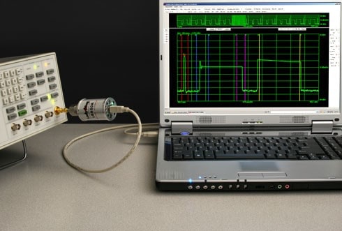
Classically, RF power sensors were used in conjunction with a separate power meter. They are slower, cost more, require more rack space and require a complex zero and measurement calibration procedure before use. Further they were often limited to measuring only true average RF power. The introduction of the USB RF power sensor (see Figure 1) has brought several advantages to making RF power measurements. These sensors are fast, low cost, compact, sophisticated and easy to use. Simply connect to a computer and you are up and running. Available USB sensors are fast, accurate, and have a full set of measurement capability. Measurements range from simple CW to modulation analysis to full featured pulse profiling and time domain gated analysis. Such features are all available with the LB480A USB sensor from Lady Bug Technologies.

Figure 1 – USB power sensor and pulse profiling software

Applications for Power Sensors

RF power measurement is fundamental to the development and verification of any wireless communication system whether it is terrestrial or satellite based. Radar or electronic warfare systems and their components in aerospace and defense applications have always had the need for accurate power measurement. Power Sensors are used during all phases of the product life cycle including design, integration, test, calibration and repair. Different use models include bench usage, portable situations, remote sensing, remote access and large embedded systems.

Generally, RF power sensors provide a terminating measurement. There are applications where in-line measurements are required such as continuous monitoring of a signal or scalar reflection and transmission measurements. A coupler or bridge with an attached sensor can serve this purpose.

USB Sensors versus Classic Sensors & Meters

  • 1. Cost & Flexibility: Prices of classic power sensor and meter combinations roughly run between $5k and $8k for the meter alone and an additional $2k to $5k for the sensor. A USB sensor ranges only from about $2k to $5k. A computer is needed for display and recording of the power measurements but often one is already available which makes USB sensors very economical. Also, a single computer can be used for multiple sensors.
    USB sensors provide flexibility due to their compact size and light weight enabling them to be used in applications in which classic sensors and meters are completely unsuited. Not needing to be tethered to a meter opens the door to uses involving multiple sensors embedded not only in test systems but in field deployed operational systems as well.
  • 2. Rack Space: Classic power meter consume valuable rack space since one meter can at most support two sensors. USB sensors require only a single computer. Multiport scalar measurements can easily be made through the use of a USB hub making port replication simple and inexpensive.
  • 3. Remote Operation: Classic sensors require a meter to accompany the sensor and the distance between the measuring sensor and the display meter is limited to the length of the sensor cable. This is typically about 3 feet with extensions available. For USB sensors the length from the point of measurement to the USB port on a computer or hub can be up to 5 meters and with a USB extender can be up to thousands of meters. These lengths allow for easy operation at antenna sites, embedded in a test system and other remote sensing applications.
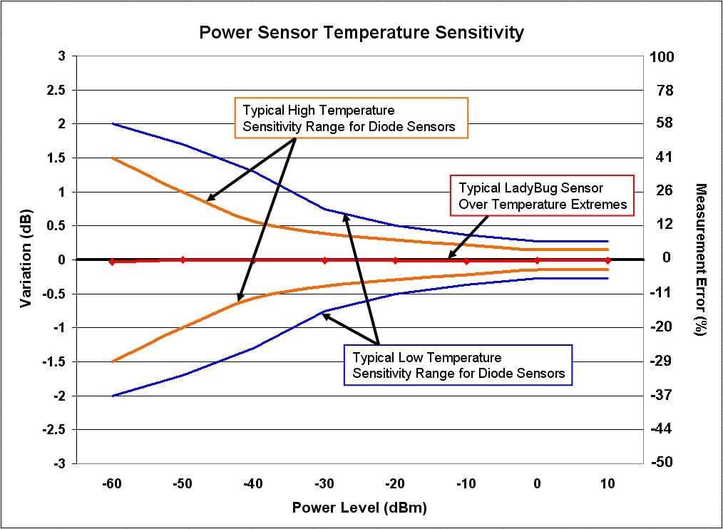
  • 4. No-Zero-No-Cal: Most USB power sensors require an internal zeroing periodically. The line of USB sensors from Lady Bug Technologies has made the internal zero & calibration processes obsolete with the ability to make highly accurate measurements without the need for zero & cal. They undergo the most rigorous factory calibration in the industry including a calibration across the full operational temperature range. Then during use, the sensor measures the temperature for each power reading, employing a patented technique to ensure that the correct factory temperature calibration factor is always applied to each measurement.

Figure 2 – Temperature sensitivity of a Lady Bug USB sensor versus classic diode sensors

Accuracy and Measurement Uncertainty

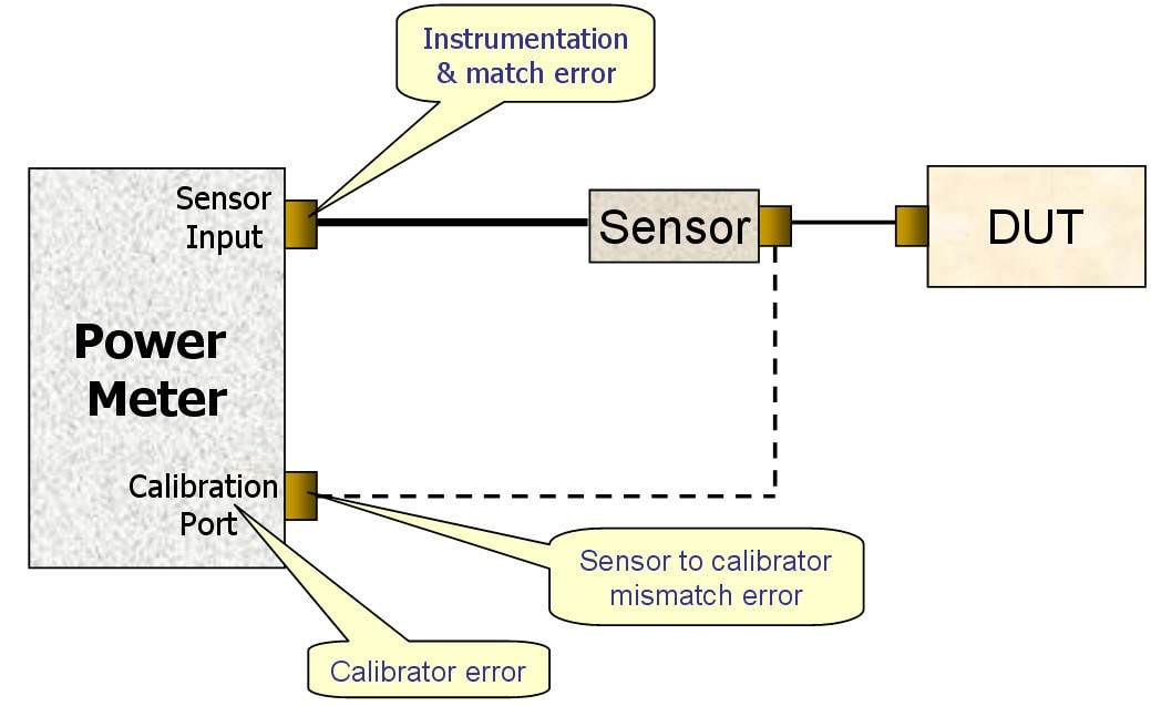
Several different error terms go to make up the accuracy or measurement uncertainty specification of a power sensor. The list below indicates the most significant ones. Figure 3 shows errors that are unique to the classic power meter & sensor combination not present with USB sensors.

  • 1. Calibrator: Typically about a 2% error contribution, the calibrator within the power meter has its own set of errors. This error is not present with USB sensors
  • 2. Sensor calibrator mismatch:The connection to the calibration port on the meter is another source of inaccuracy. This error also typically runs about 2% and is also not present with USB sensors.
  • 3.Meter to sensor match and instrumentation error:There is an error of roughly 0.5% from the interconnection of the meter and sensor as well as the contribution from the meter itself. This error term is also not an issue for USB sensors.
  • 4.Sensor to Device Under Test (DUT) mismatch and repeatability: Often the largest error at about 2 to 3 %.
  • 5.Calibration Factors: Another large error of about 2%. This uncertainty stems from drift and inaccuracy within the standards, instruments and other devices used during the calibration process.
  • 6.Linearity:For RF power sensors the detected power is not always linearly proportional to input power. Generally, the non-linearity of older sensors ranged up to 7% but in newer sensor its roughly 3 %. Most of this error can be removed through new design innovations and calibration.
  • 7.Noise: The contribution of power sensor noise to measurement uncertainty is most significant at lower power levels, generally within about 20 dB of the sensor’s minimum power rating.
  • 8.Temperature (larger or zero and cal vs. small no-zero-no-cal): Changes in temperature can cause large errors in power measurements, particularly for very wide temperature variations (See figure 2). For sensors that do not need a zero and measurement calibration (cal) the temperature sensitivity is much lower than those classic sensors that do require a zero and cal.

Figure 3 – Accuracy errors unique to classic power meters and sensors that USB sensors do not have

Dynamic Range

The total dynamic power range of a sensor is directly related to the linearity of the sensor used. Sensors are available that can cover a range up to 90 dB. There are several methods used to extend the dynamic range of diode power sensors beyond the linear portion of their square-law region. One popular method involves using a multiple diode path architecture that incorporates two or more diodes with different square law characteristics to extend the range. Another method, sometimes used in conjunction with multiple paths, is to use switched attenuators to maintain the signal level within the diode’s linear region. And, of course to some degree, calibration factors are utilized. These calibration factors must account for not only the input power level input but also the input frequency and temperature of the sensor at the time of the measurement. This results in a three dimensional table of calibration factors to cover the power, frequency and temperature ranges specified for the sensor

Frequency Range

Power sensors are available in a variety of frequency ranges that cover bands from 9 kHz to 110 GHz. The most common bands are from 10 MHz to 40 GHz. Variations in the frequency response of the sensor are accounted for in the calibration table stored within the sensor.

Zero & Cal

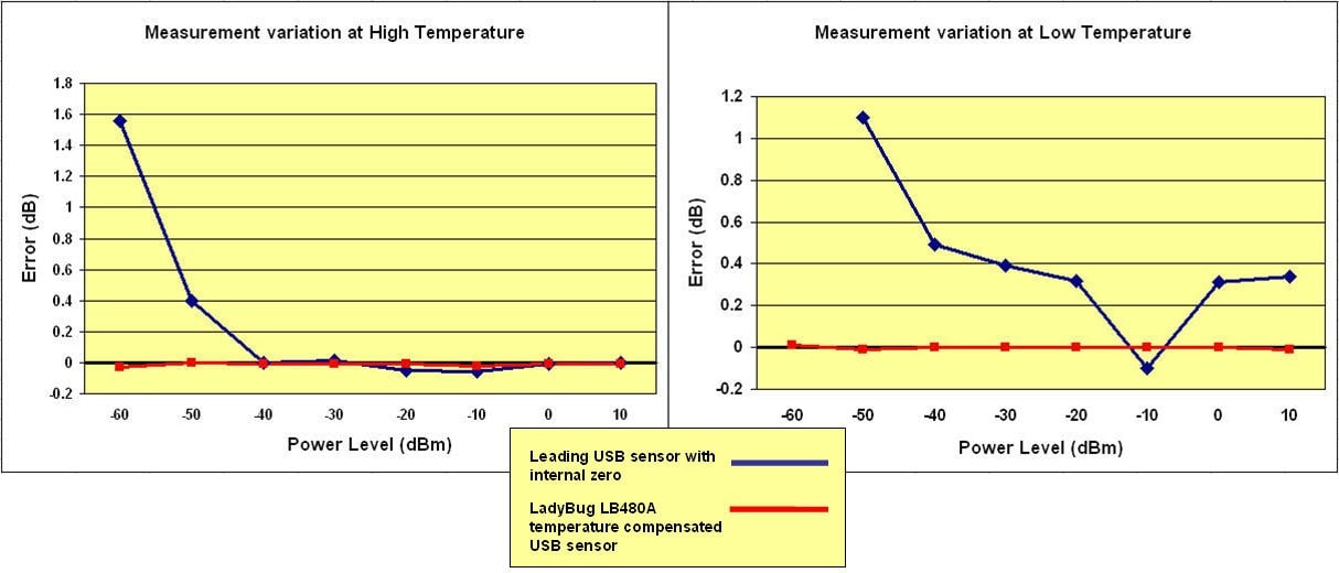
The zero & cal process for traditional power sensors involves multiple disconnections from the measurement point and connections to an external calibration source. By themselves zero & cal do not provide an accurate power measurement even when executed after each change in temperature. Newer sensors that have an internal zero & cal capability don’t require an external calibration source but also exhibit sensitivity to temperature. In this case, the internal zero & cal is automatically performed periodically but not for each measurement. The sensitivity of a USB sensor with internal zero is shown in Figure 4. Notice that for the lower power levels, the measurement error climbs higher than 1.5 dB and represents a measurement error of over 40%.

Figure 4 – Temperature sensitivity of a typical USB sensor with internal zero versus the temperature compensated USB sensor from LadyBug Technologies

Sensors from Ladybug Technologies undergo a rigorous calibration process and are fully temperature compensated so there is no need to cal or zero the sensor.

Measurement Capabilities and Features

  • 1. Measurement Speed: Often a sensor will have its sample rate specified, but the more important parameter to note is settled measurements per second. The number of readings or measurements per second varies widely between different sensors depending on the integration time required to get a stable measurement from the sensor being used. Lady Bug USB power sensors have the ability to make a settled measurement at -60dBm in roughly a single millisecond. The typical settling time for a classic sensor are generally greater than one second and could be as much as three to four seconds. To analyze higher bandwidth signals, such as a bursting or pulsed waveform, power sensors may use under-sampling techniques to increase the effective sample rate and analysis bandwidth.
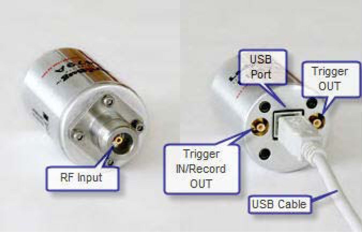
  • 2. Triggering: Triggering is necessary for some applications but not all sensors provide this feature. Synchronizing the sensor sampling with data clock of the device being tested is critical for measurement of waveform with complex modulation. A trigger is also needed to synchronize the measurement with another instrument or change in the waveform such as frequency steps. Trigger ports on a USB sensor are located on the sensor itself (See Figure 5).

Figure 5 – Trigger In/Out ports on the Lady Bug Technologies USB sensor

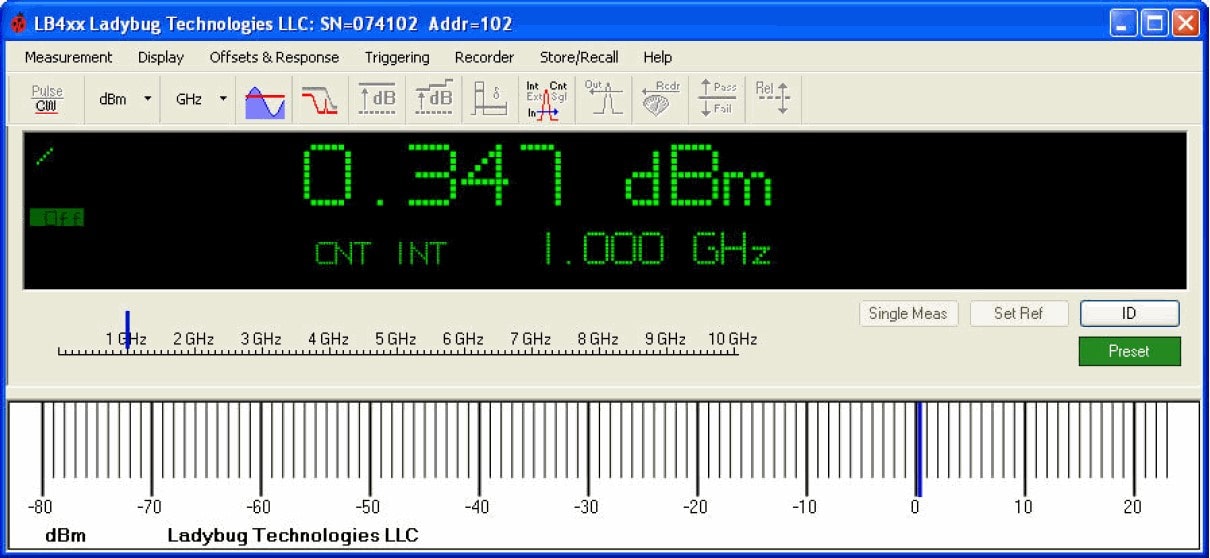
  • 3. Software features for USB sensors: Most USB type sensors come with measurement software. Although the user must provide the PC adding cost to this alternative, a single PC can support multiple sensors. This makes an economical alternative to classic power sensors and meters. In some instances the software available can do much more than simply act as a meter display. Addition functions could include strip chart recording, pulse profiling, scalar analysis, crest factor measurement, and a variety of math functions for multi-sensor configurations. Figure 6 shows a typical PC power meter display.

Figure 6 – PC power meter display for a USB sensor

Conclusion

When selecting a power sensor, much depends on the application. But beyond the needed dynamic range and frequency coverage there are many aspects to consider when making a choice. The accuracy and uncertainty that can affect the measurements need to be clearly understood in terms of the application. Will there be wide temperature variations? Will the sensor be connected and re-connected often? Will many different devices be measured such that mismatch may be an issue?

Another decision to be made is whether the convenience of an USB sensor is needed or a traditional sensor/meter configuration is appropriate. If portability is important, or the sensor is to be embedded in a system, or remote measurements are needed, then a USB sensor may be your best choice. The PowerSensor+ USB sensors from LadyBug Technologies deliver high performance in terms of accuracy, settling time and stability over temperature at the lowest price in class.